A standard Saab turbo 16 engine with its 160 horsepower (175 in cars without catalytic converter) is surely not a rocket engine. On the other hand, like many other turbocharged powerplants it has a very good potential for simple and cheap performance increases. Unlike most other turbocharged engines from 80's and early 90's the Saab B202 engine has quite an advanced electronic control system, the turbo boost control module of it is called APC - that's a magic word in the Saab circles. Because of this (as you'll see) performance tuning a Saab doesn't neccessarily mean getting your hands dirty... I had to separate this page into four sections, the links are below.
Wrote an email about setting the timing and optimizing it with the BTM to a fellow enthusiast. I suppose others may find the info useful as well, so here's the email.
I had heard several positive comments about MSD's boost timing master at the Saabnet. As two other local Saab-hobbyists were interested in getting the box, we sent group order to Summit Racing. Summit's price was very competitive. In Finland these boxes are available locally from US-Parts, but the availability and pricing is, eh, a little problematic. The box is very simple to install: just a few wires intercepting the current to the coil. The box takes in one vacuum hose from the inlet manifold. Based on the pressure on the hose, it will retard the ignition timing (on a scale of 0-3 deg per 1 PSI of boost). BTM enabled me to raise the ignition advance from 14 (which I had to use to avoid detonation at high boost) back to the 16 which is the stock value. This alone did wonders for the low-end torque and proved the box was worth the money. I tweaked the standard vacuum advance to bring in only 2.5 degs of retard (standard is about 5 deg) and dialed a little bit of extra retard from the BTM. Up to this point I was smart, from this point forward not so, it turned out: Whenever messing with the timing you should always MEASURE where you're at, not only estimate! I THOUGHT I had an optimal timing curve, but as it turns out, it sucked big time. Now that I look back I used to be very happy with only the BTM. But after my further investigations (see below) I cannot recommend just bying the BTM and plugging it in. You really need a timing lamp and lots of patience to make things right! A pressure control valve may be of use, as well.
I drove around with the BTM box and "estimated" timing curve for almost a year, but now in summer 2001 I decided to do some further investigation. I purchased a timing light and a pressure control valve. This valve, seen on a picture on the left, is similar to the ones used in air compressors. It takes one input hose and an output. The pressure going from the input goes directly to the output, until a predefined level. After the preset pressure level has been reached in the input, the output pressure will remain there. And as soon as the input pressure gets below the preset level, the output pressure will follow.
A VERY important thing to note about the pressure valves is that the ones I have tested are very linear in operation by means of transmitting the increased pressure from the input to the output of the valve. But unfortunately it is not like that the other way around: Once the pressure at the output has reached the level set with the valve, that level will stabilize. The problem is that it may remain stabile even if the pressure at the input DOES GO DOWN! This can lead into a situation (closed throttle for example) where the BTM is still retarding even though the boost's down already - you DO NOT wan't that to happen! This is a problem only if the pneumatic circuit at the output is a closed one, i.e. there's nothing there that consumes the air. This is exactly the case with the BTM!
Checking what your valve does is very simple: attach a pressure gauge to the output of the pressure valve. Introduce pressure into the input of the valve. Note the pressure reading at the gauge. Now disconnect the pressure source. Look at the gauge: still got that pressure in there? If so, you need the following fix...
My suggestion: the "right" way of connecting the hose terminals into the pressure control valve is by using sealing tape at the threads. That's ok for the input side. But I recommend skipping the tape at the output threads. This will create a very small leak which will bleed the "ghost" pressure left in the hose into the atmosphere. With this trick the output will follow the falling pressure at the input with no delay at all.
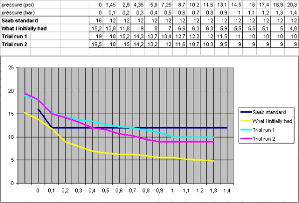
The idea in fitting the pressure valve is to control the peak pressure the BTM will see. This really is neccessary to optimize the ignition curve. BTM, since it is linear in operation, will always add too much top-end retard if you wan't to have enough retard in low boost. I did several experiments with different timing settings, this time without taking the car to a dyno (there really are differences you'll be able to feel in your pants, of course the dyno would give more accurate results). Without bothering you with all the different results, below is a chart concluding what I found to be best for my purpose.
Here are the settings I'm using:
- ignition timing 19,5 degs at idle
- one degree of mechanical retard at about 2 PSI
- Rest of the retard is from the BTM box
- BTM's input is limited to 1 bar / 15PSI with the pressure valve
With this setup, the timing will retard from the relatively high level of 19.5 degs at atmospheric pressure to 9 degs at 1 bar. I did experiment with a higher advance, but at 10 degs @1bar/15PSI the APC was sensing knock and dropped the boost. It seems that 9 degs is good for at least 1.2 bars / 17PSI which is the pressure I've set the APC box at.
In December 1999 while investigating the boosting problems I decided to replace the Bougicord ignition cables. Even though they were just one year old, I suspected they were causing a problem. I looked at the various alternatives in the marked and noticed how many people out there are marketing all sorts of wonder-wires. I was convinced by Magnecor of USA. They make wires with resistance-controlled copper conductors and 100% silicon insulation - without forgetting the RF filtering. I bought a set of their KV-85 Competition wires for $90. Before installing the wires I was very sceptical about them making any difference. I was very surprised when test driving my RPK after the replacement: The boost got so high that the pressure cutout switch operated! And I surely didn't tweak the pressure pot before this! I had to adjust the pressure a little lower - and was convinced that the $90 was well spent. Soon after that I experimented with the ignition timing and concluded that 14 deg. worked best for 17PSI max boost. Of course it does affect the fuel consumption and low end torque (both for worse) a little, but guaranteed a much more stable high boost. Update: 14 degs has been history for a while now. BTM works great!
Complete ignition wire kit tailored for Saab 16-valve engines. 8.5mm wires with copper core and RF insulation. Red silicone.
Vacuum hoses
Last Update 22nd June 2000
I had been a little worried about the condition of my vacuum hoses for a long time. When I purchased my AC system from Saab Savior I decided to order a silicon hose kit at the same time. For $64 I got a complete set of hoses in red silicon. They were a quick and simple install, and as I suspected I found at least two badly cracked hoses. The "funniest" thing was that the worst crack was in a hose leading to the fuel pressure regulator: it may have caused enough pressure loss in high rpms to make the FPR mix too lean a mixture: I can only speculate where that could have leaded in a long run.
Silicone hose kit: hoses for APC solenoid, brake assist servo and all of the smaller hoses in the engine compartment. Easy to replace, should have done mine sooner.
About the plots:
-Trial run 1 was not actually the first one, of course, but I was so happy with it that I almost settled for it.
-Trial run 2: did this one just to see if there's anything more to gain. Turned out that this tiny difference in timing made a big difference with the stability of the boost: with 10 degs the boost was very unstable right around 1 bar/15PSI, but the addition of 1 tiny deg of retard helped a lot!